
08 - Advanced Assembly for the Drawing Machine
Production guide
- Step 1 of 30
From the workbench to the workshop
These notes record how Robot In A Can prepared the wooden Drawing Machine kits for Festival NUM in November 2026. They cover the motor and switch, the gear axles and the four bamboo pins. You’ll need the matching wooden plate, gears, arms, rings and feet. Once the parts are ready, use Assemble the Drawing Machine to finish the build.
NoteAsk an adult to do the soldering, hot gluing and cutting. Wear eye protection when cutting bamboo. Keep the batteries out except during the short tests, and keep fingers clear of moving gears.
- Step 2 of 30
1. Wire and mount the motor
For this part, gather the back plate, geared motor, battery holder, three-terminal slide switch and test batteries. You’ll need a soldering iron, solder, flux, wire cutters, wire strippers and a hot-glue gun. Keep the batteries out while you work.
- Step 3 of 30
Solder the motor wires
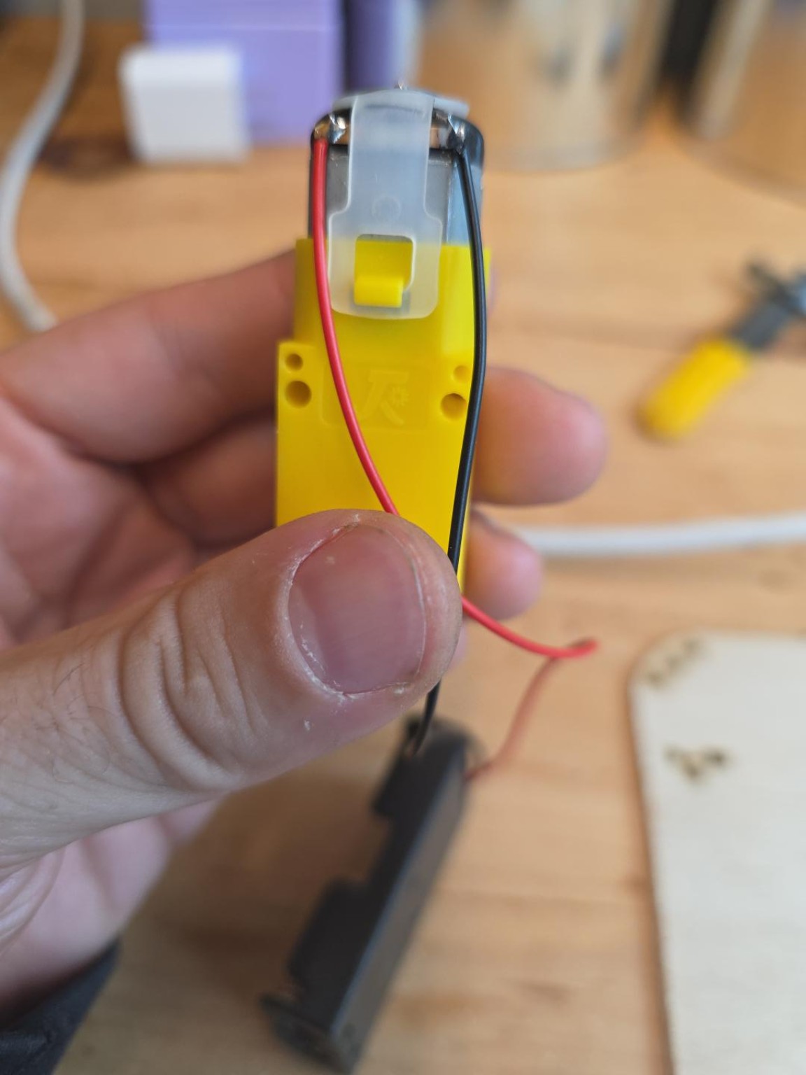
Keep the batteries out. Hold the motor with the metal can up, the yellow gearbox down and the metal strap facing you. Solder the red battery-holder wire to the left terminal and the black wire to the right. Tug gently on each wire. Check that no stray wire or solder joins the terminals.
- Step 4 of 30
Reinforce the motor connections
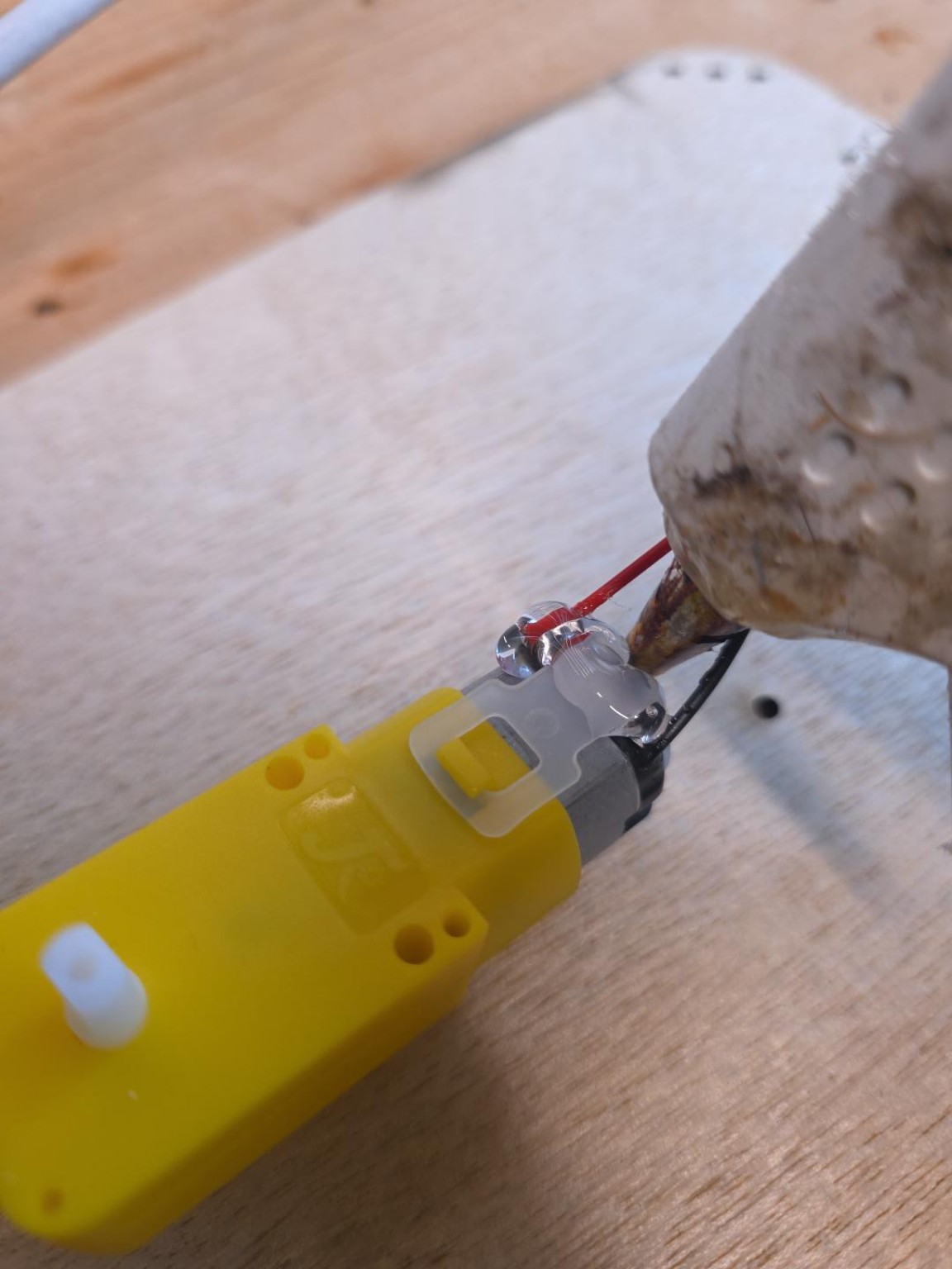
Turn the plate underside up and set the switch aside. Gently bend the wires away from the motor. Cover the solder joints and nearby wire ends with hot glue. In the same operation, add glue at the motor assembly’s highest contact point and just above the shaft. Keep glue off the shaft.
- Step 5 of 30
Mount the motor under the plate
While the glue is hot, flip the motor glue-side down onto the underside of the plate. Centre the shaft in the round motor hole. Hold the motor still until the glue sets.
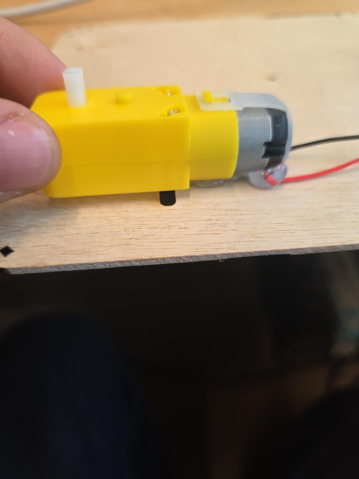
- Step 6 of 30
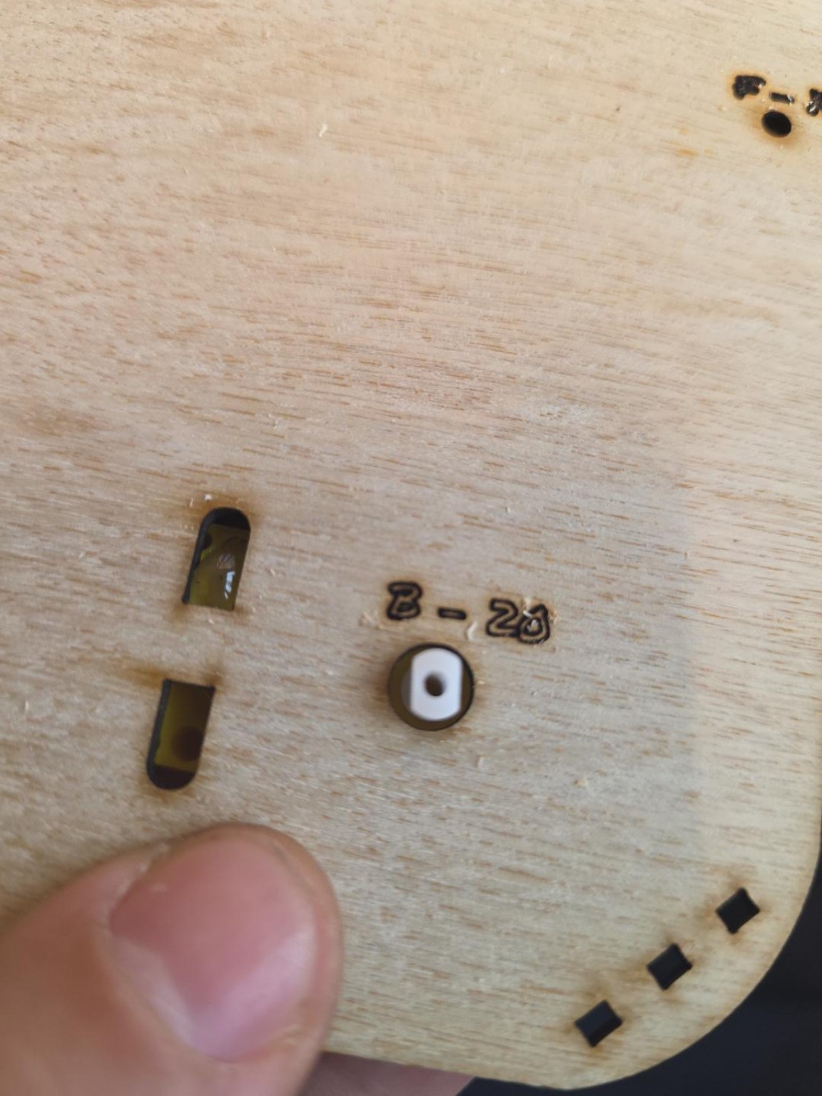
Check the shaft from above
Look at the labelled side of the plate. The motor shaft should sit in the middle of the round hole marked B20. Check that there’s room for it to spin without rubbing.
- Step 7 of 30
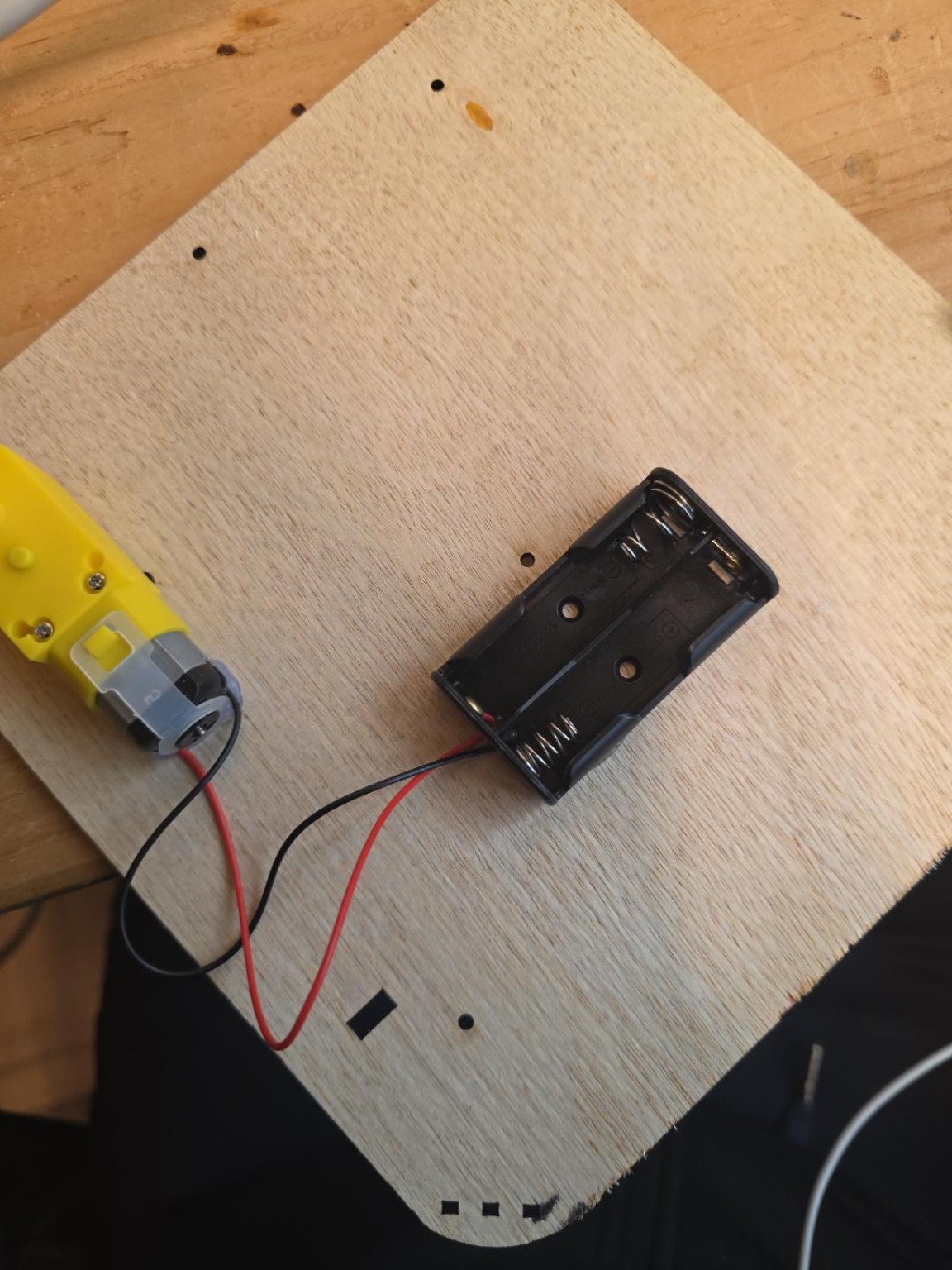
Attach the battery holder
Put two dots of hot glue on the flat underside of the holder, one near each end. Keep glue out of its holes and battery slots. Press it onto the underside of the plate. Line up the pair of holes in the middle of the holder with the A60 centre hole as shown. Hold until set and check that the wires are free.
- Step 8 of 30
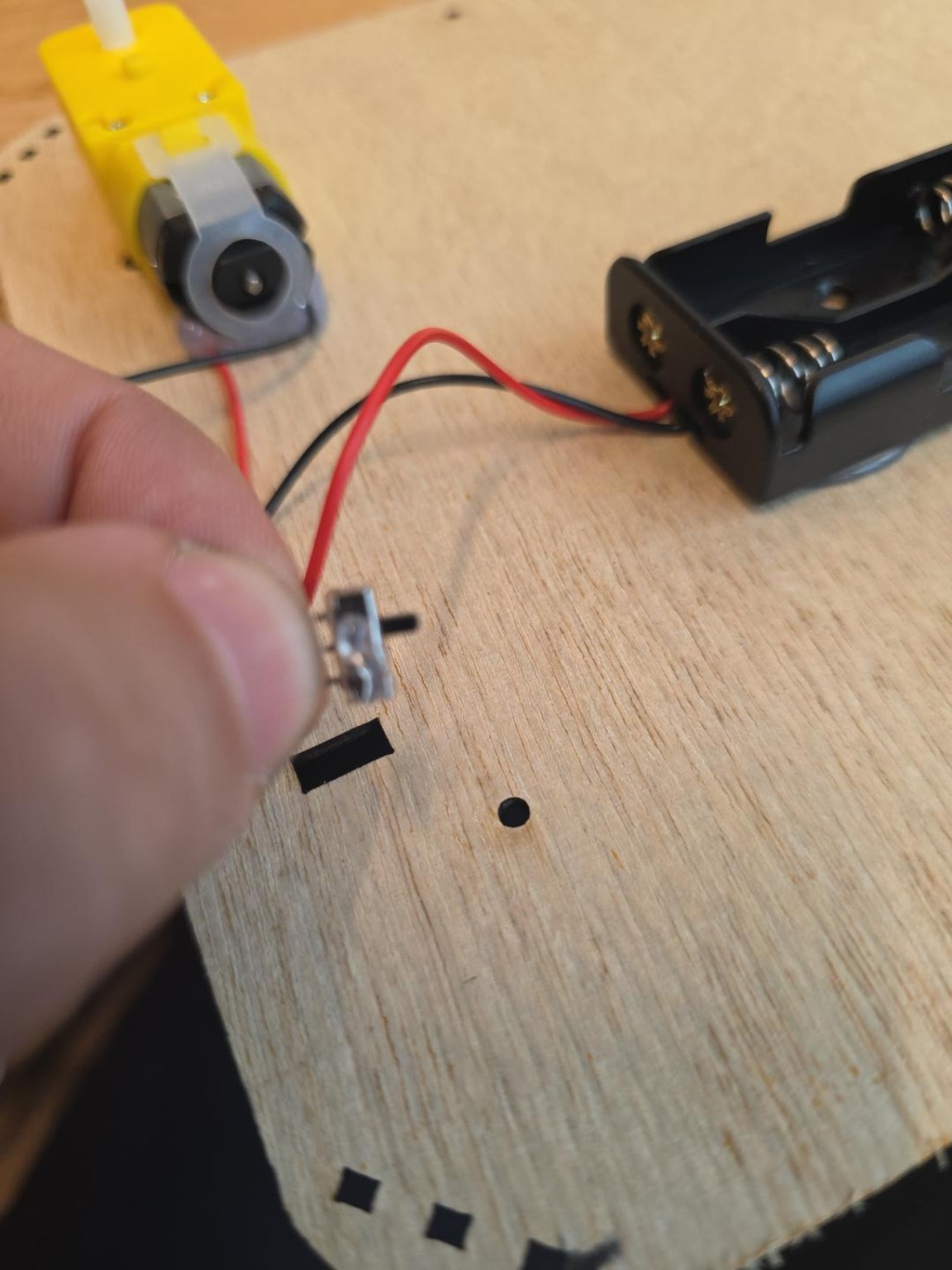
Put the switch in the slot
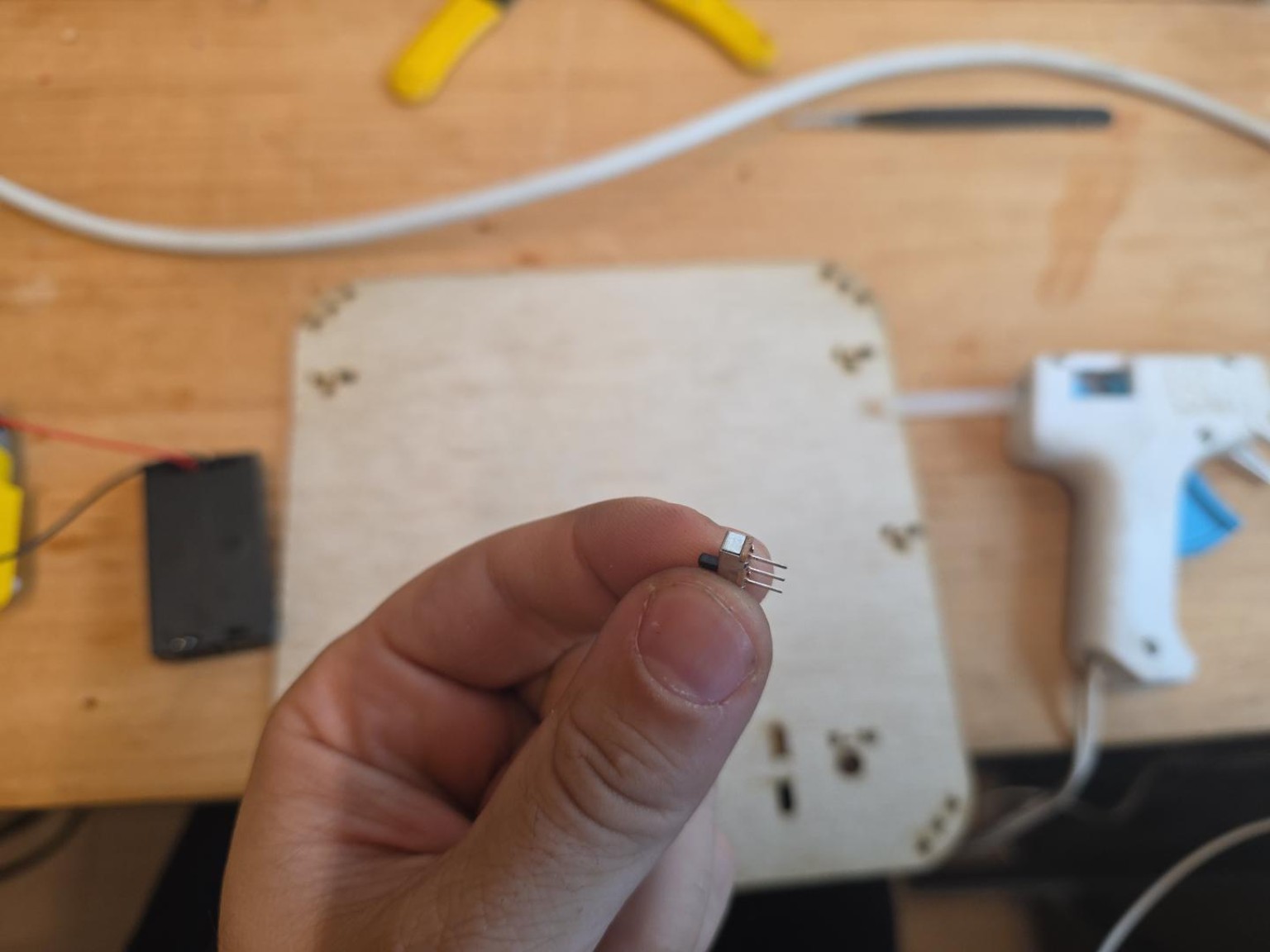
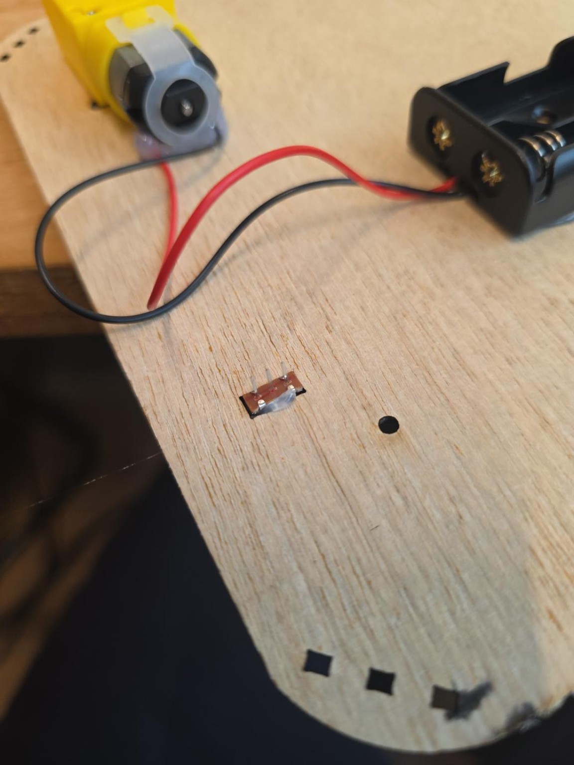
Put a small dab of hot glue on the switch body. Keep the lever and terminals clear. Insert the switch in the rectangular slot with the terminals facing the underside and the lever accessible from the top.
- Step 9 of 30
Seat the switch and check the lever
Seat the switch evenly in the plate. Hold it still while the glue sets. Slide the lever all the way in both directions to check that it moves freely.
- Step 10 of 30
Cut and prepare the red wire
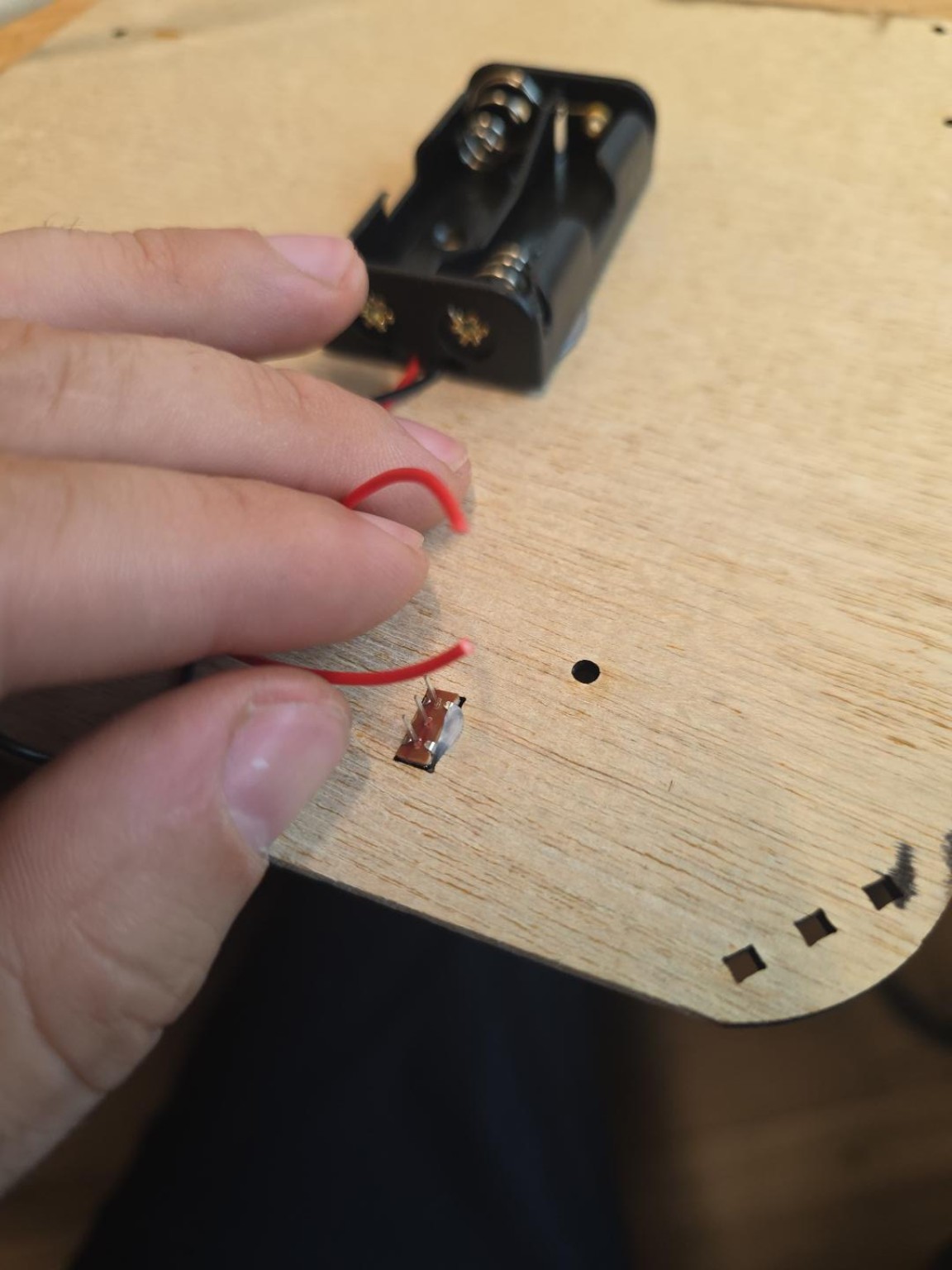
Cut the red wire near the switch. Leave enough slack for both ends to reach their terminals. Leave the black wire whole. Strip a short length from each cut end. Apply flux to both exposed tips and to the switch terminals you’ll solder.
- Step 11 of 30
Solder the switch
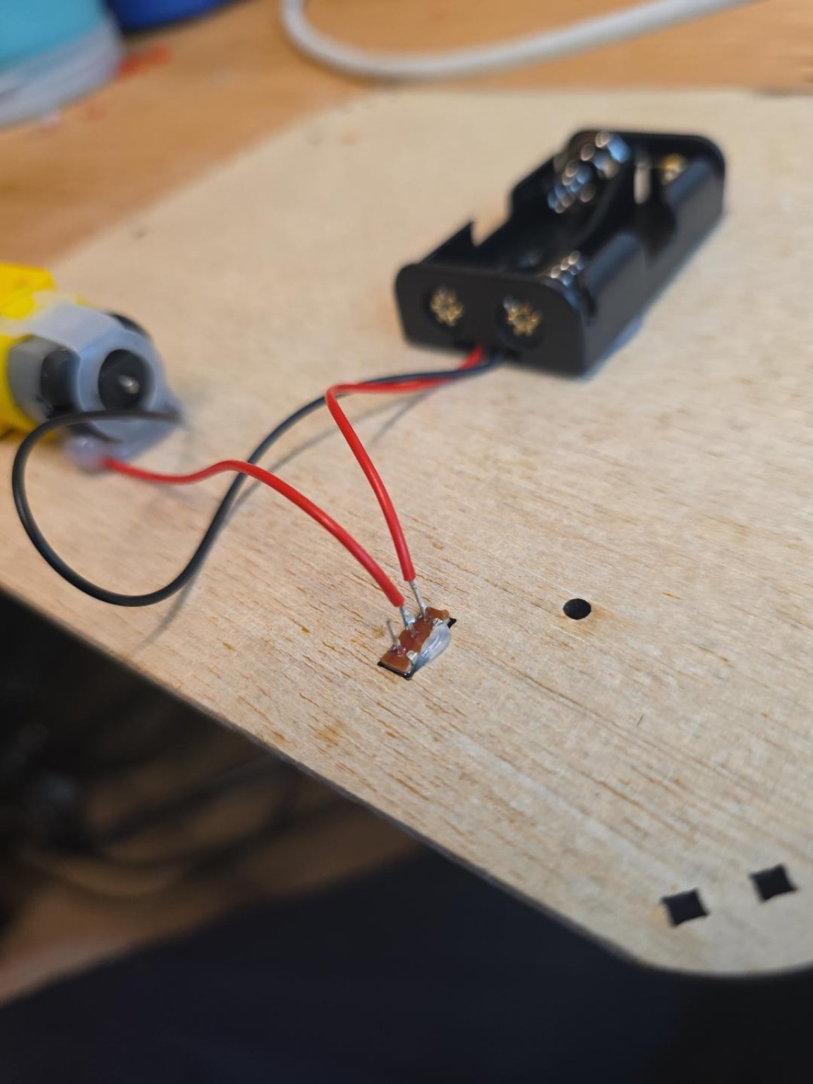
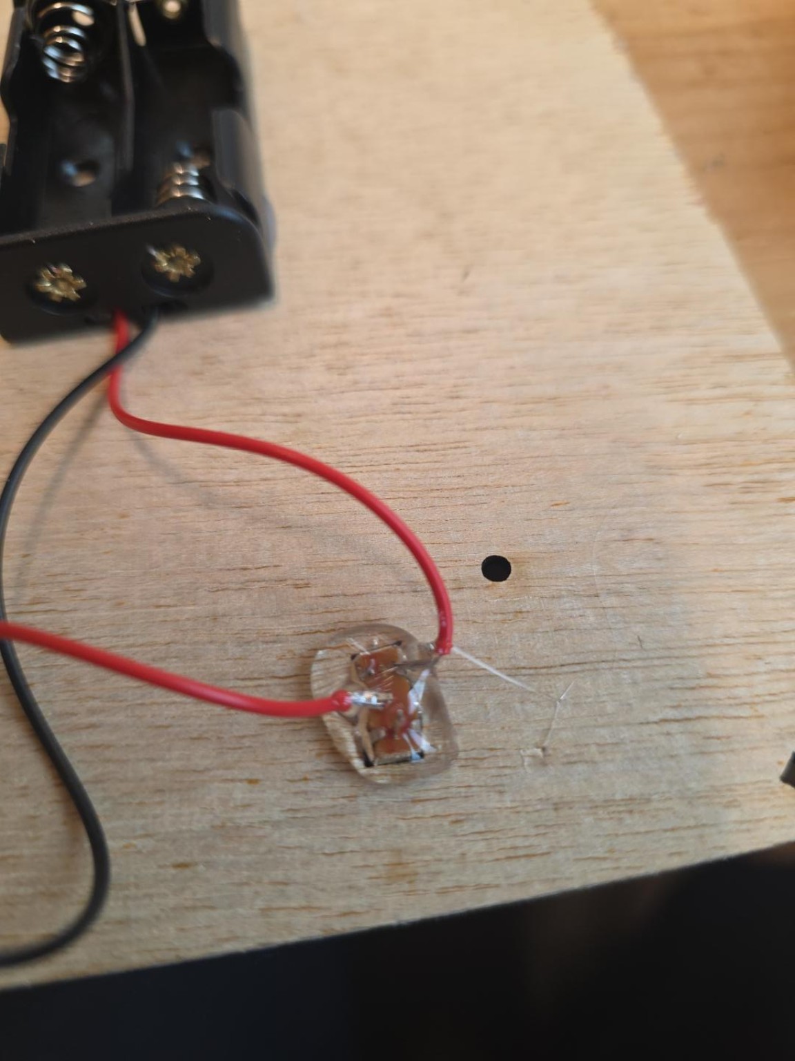
Coat both bare wire tips with a little solder. Support the plate with the switch just past the table edge. Solder the red wire from the battery holder to the outer terminal shown at the top of the photo. Solder the red wire from the motor to the middle terminal. Leave the other outer terminal empty. Heat each joint briefly so the glue stays firm. Let everything cool, then check that the joints hold, stay separate and leave the lever free.
- Step 12 of 30
Test the motor and fold down the terminals
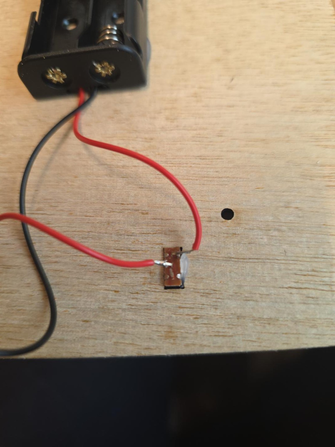
Put in the batteries, matching the + and − marks. Check that the switch turns the motor on and off and that the shaft spins without rubbing. Remove the batteries. Support the switch and gently bend the two connected terminals flat in opposite directions. Keep them apart.
- Step 13 of 30
Reinforce the switch and test again
Cover the connected terminals and joints with hot glue. Extend the glue onto the surrounding wood and keep the lever clear. Hold the switch still while the glue cools. Repeat the on/off test and remove the batteries. Check that the motor, holder and switch are firm, the wires have slack, and moving parts and battery slots are clean.
- Step 14 of 30
2. Install the gear axles
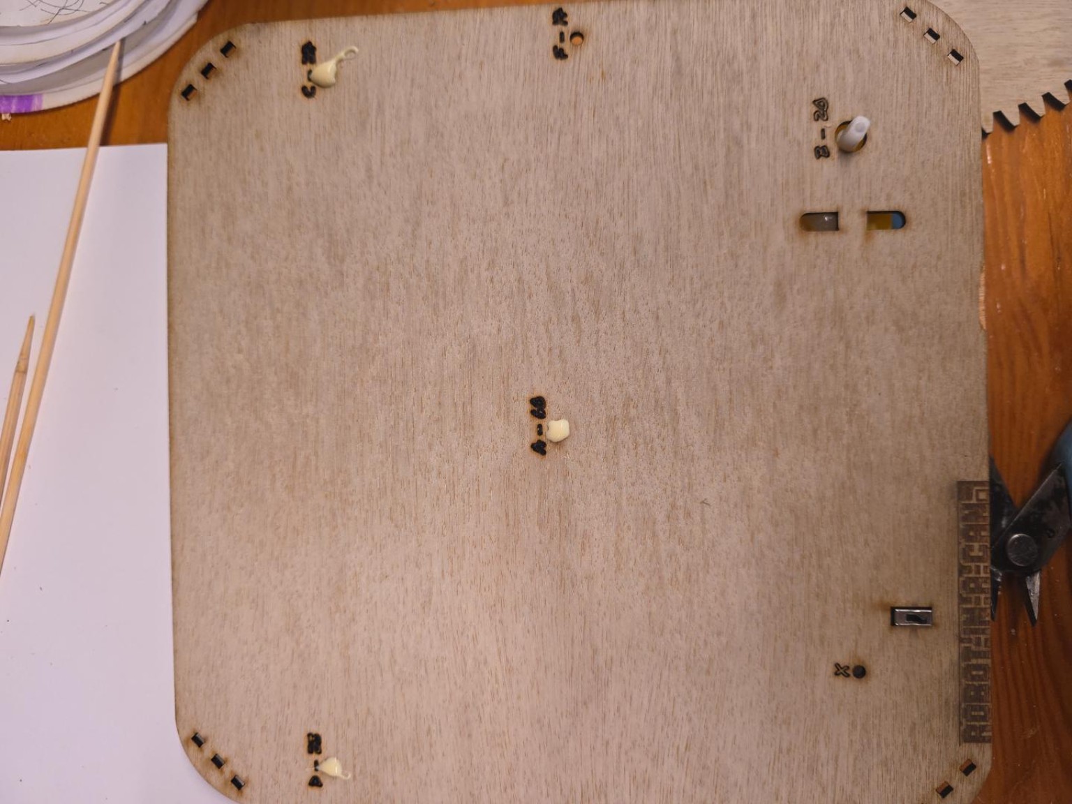
Gather three bamboo skewers, glue, cutters that can cut bamboo, gears A60, C27 and D23, and the B20 motor gear for the test. Lay the plate labelled side up. Put a small dab of glue in each hole marked A60, C27 and D23. Leave the batteries out until the powered test.
- Step 15 of 30
Insert the bamboo axles
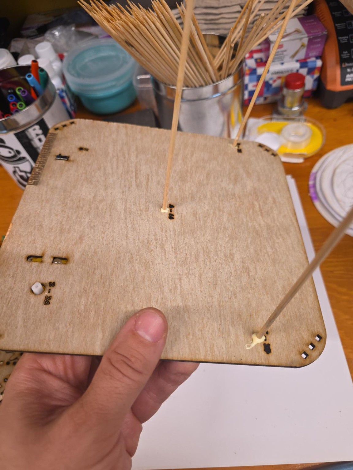
Twist each skewer gently as you push it into its hole to spread the glue. Leave just the tip sticking out under the plate.
- Step 16 of 30
Fit the gears and turn them by hand
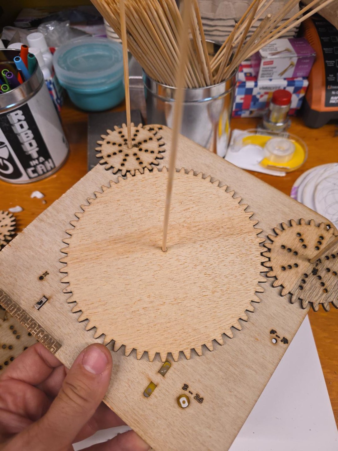
Slide A60, C27 and D23 onto their matching axles. Check that the gears lie flat and their teeth mesh. Gently turn them by hand. They should move together without catching. Keep the gears free of glue.
- Step 17 of 30
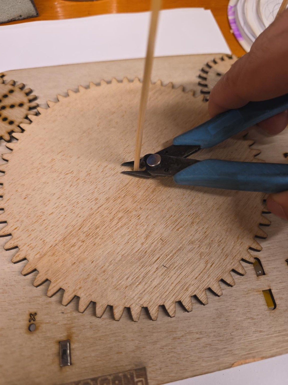
Trim the centre axle flush
Keep the gears seated flat so their top faces give you the cutting height. Cut the A60 axle flush with the top of the large gear.
- Step 18 of 30
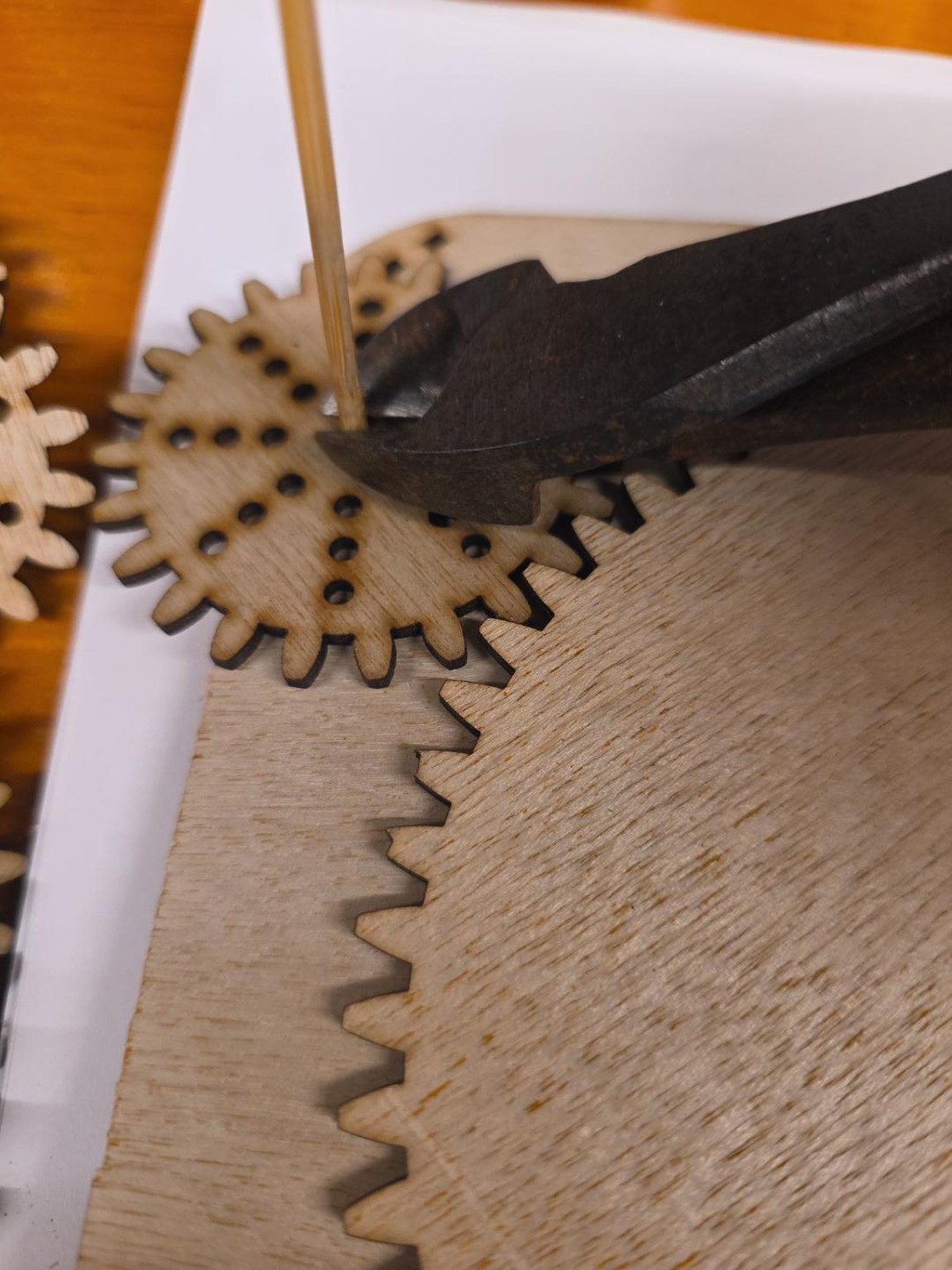
Trim the two outer axles
Cut the C27 and D23 axles a little above the top of their gears. Hold the plate steady so the axles stay in place.
- Step 19 of 30
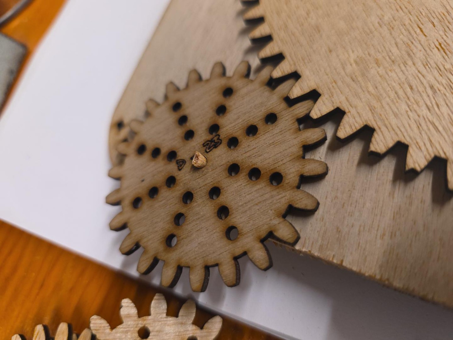
Check the axle heights
Check that A60 is flush and that C27 and D23 stick up slightly. Turn the gears by hand again. They should still sit flat and move freely.
- Step 20 of 30
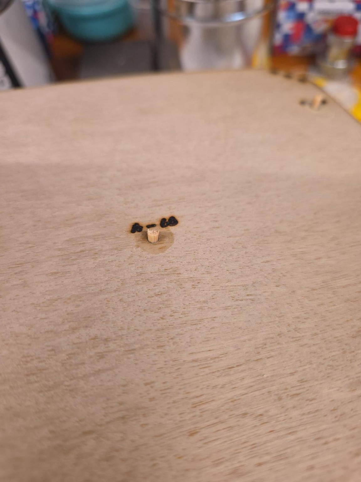
Lift the gears and check the glue
Carefully lift off all three gears. The glue around the axles should form a thin, flat layer. A lump can lift a gear or stop it from turning freely.
- Step 21 of 30
Reinforce the axles from underneath
Turn the plate over. Put a small dab of glue over each of the three bamboo ends and onto the nearby wood. Check that all three ends are covered and the axles stay in place.
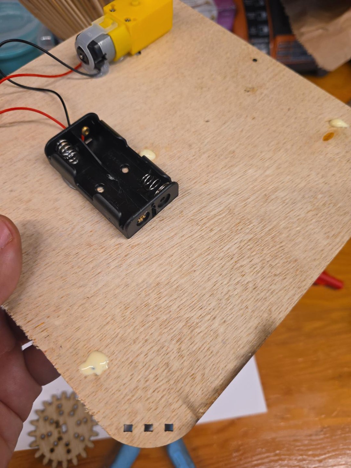
- Step 22 of 30
Run a short powered test
Turn the plate labelled side up and refit A60, C27 and D23. Fit the B20 drive gear on the motor shaft. Put in the batteries and switch on briefly. Keep fingers clear. All four gears should sit flat and turn without catching or lifting. Switch off, remove the batteries and let the glue dry fully. Set the plate down with no pressure on the axle ends.
- Step 23 of 30
3. Make the linkage and pen pins
For one kit, gather bamboo skewers, nine wooden rings about 2.7 mm thick, one wooden arm, a machine foot, glue, a ruler or callipers and a rotary tool with a suitable cutting disc. The foot gives a 35 mm length reference. Have an adult secure the bamboo and cut straight across it.
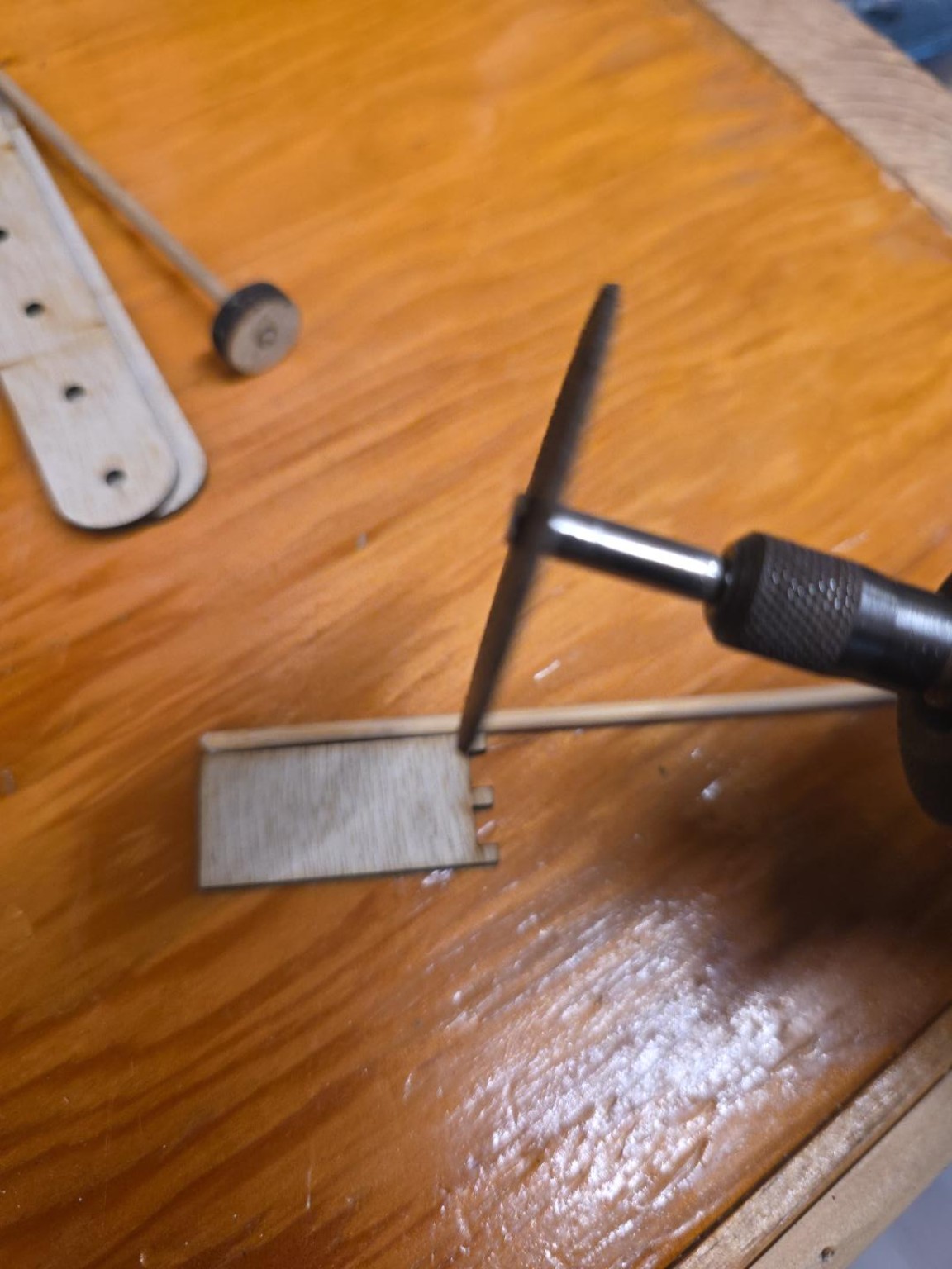
- Step 24 of 30
Cut three short pins with square ends
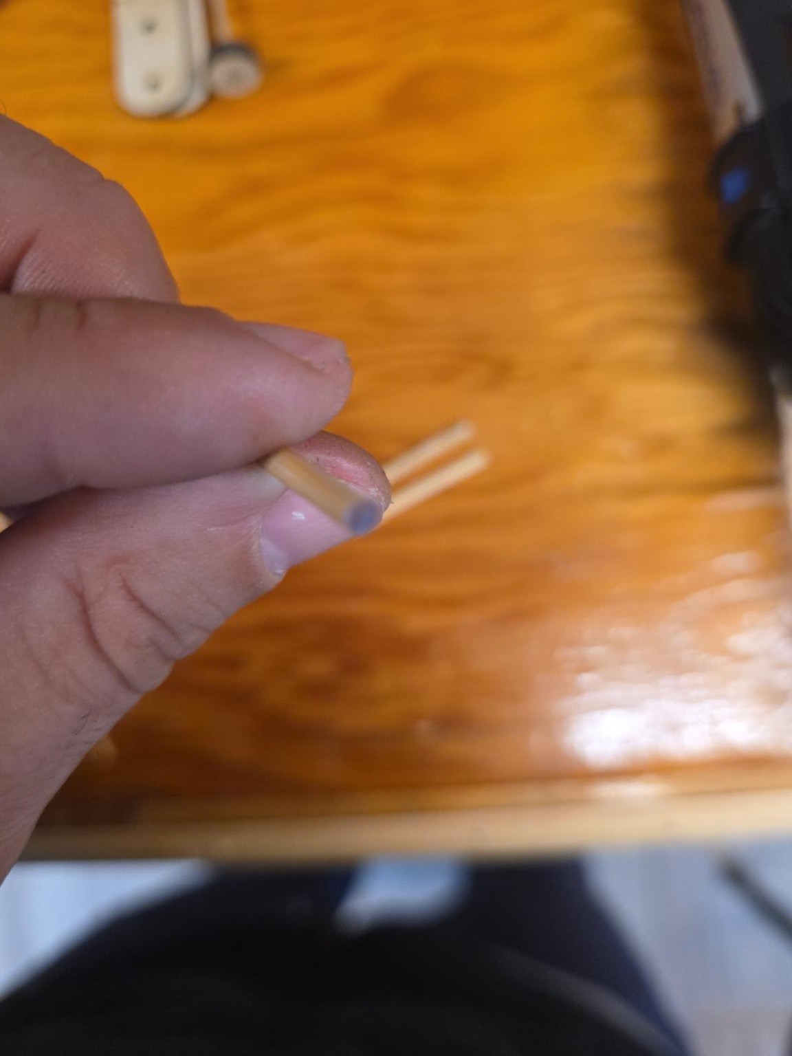
Make three pins about 35 mm long. Give each pin two flat ends cut square across the bamboo. A flat end matters more than matching the lengths exactly. Clear away splinters so the pins can sit all the way into the gear holes.
- Step 25 of 30
Glue two stacks using the arm as a guide
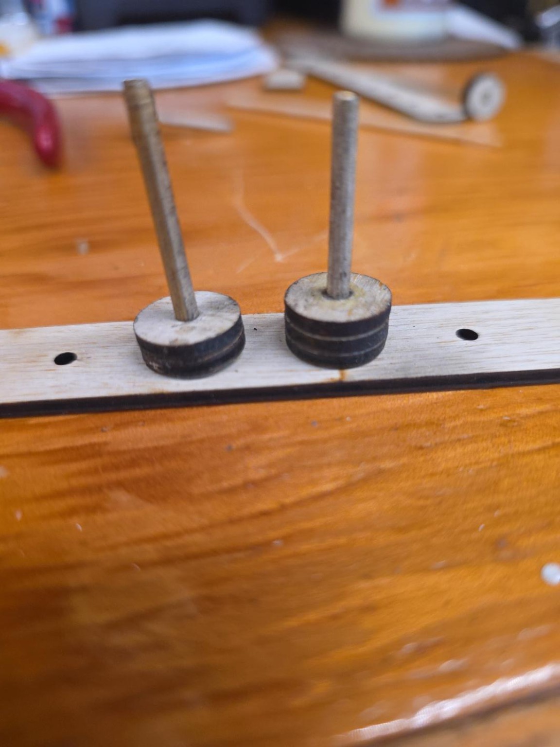
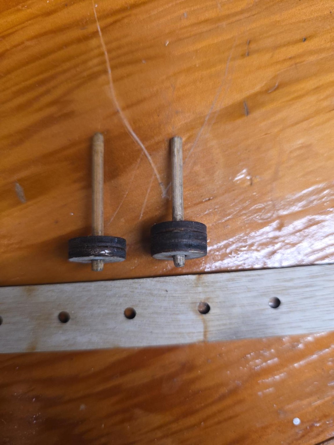
Put two short pins into holes in one wooden arm. Use the arm as a temporary guide. Stack two rings on one pin and three on the other. Put a little glue inside every ring and between each pair of rings. Press the layers flat together. Keep glue off the arm so you can remove both pins. The photos show placement and the finished stacks.
- Step 26 of 30
Leave 2.7 mm showing on both pins
Lift both assemblies out of the guide. Set each bottom tip to stick out about 2.7 mm below its bottom ring, about the thickness of one arm. Keep these tips free of glue so they fit all the way into the gear holes.
- Step 27 of 30
Make the short pin with a flat bottom
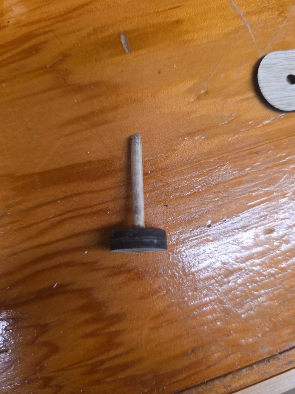
Glue two rings onto the third 35 mm pin. Add glue inside the rings and between the layers, then press them flat together. Line up the bottom of the pin with the underside of the lower ring. Check that the base is flat and free of glue lumps.
- Step 28 of 30
Make the 85 mm pen-support pin
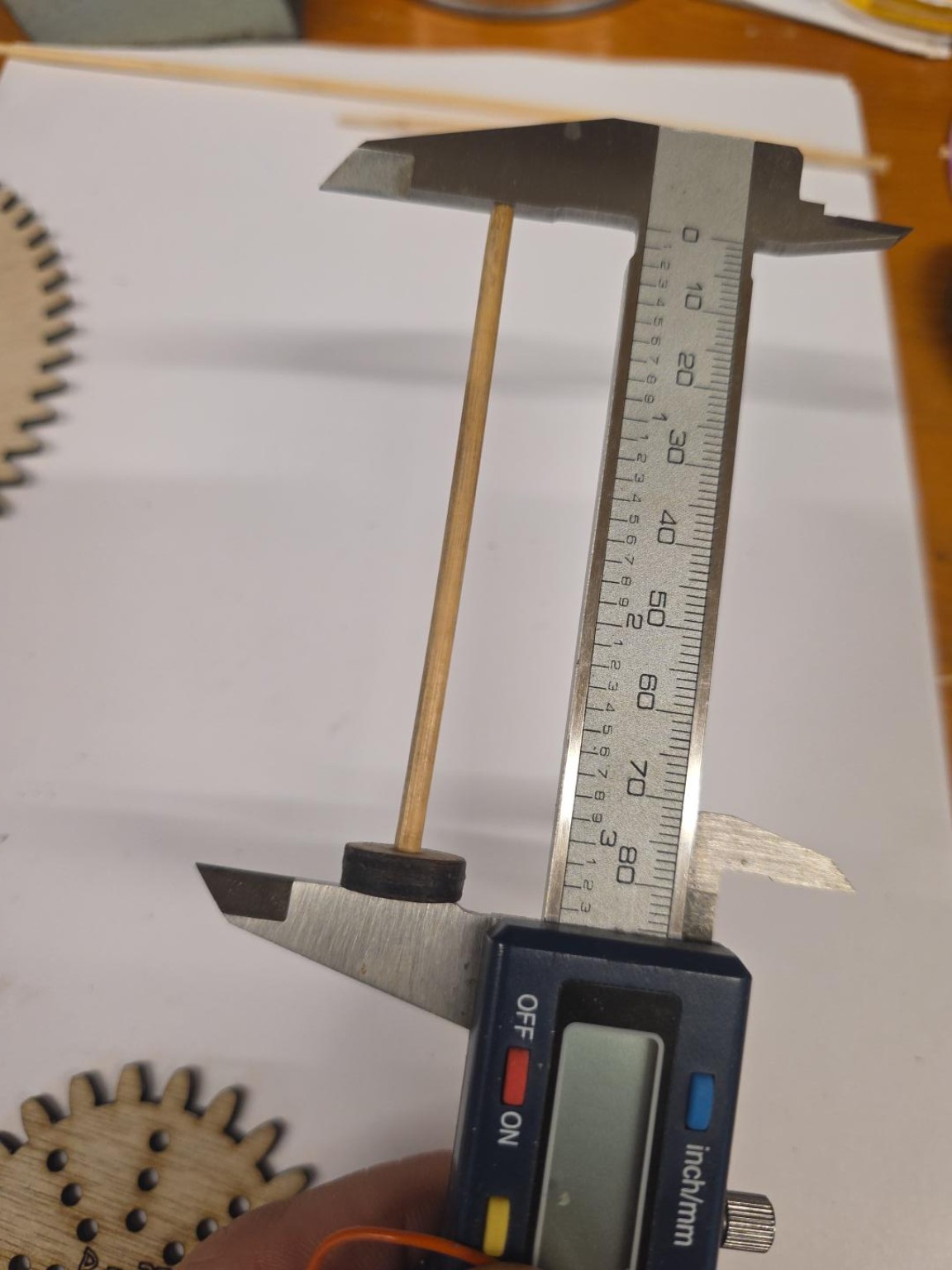
Cut one pin to 85 mm with flat, square ends. Glue on two rings using the same method. Keep the pin flush with the underside of the bottom ring. Check the full length from end to end with a ruler or callipers. Check that the bottom is flat.
- Step 29 of 30
Check all four pins
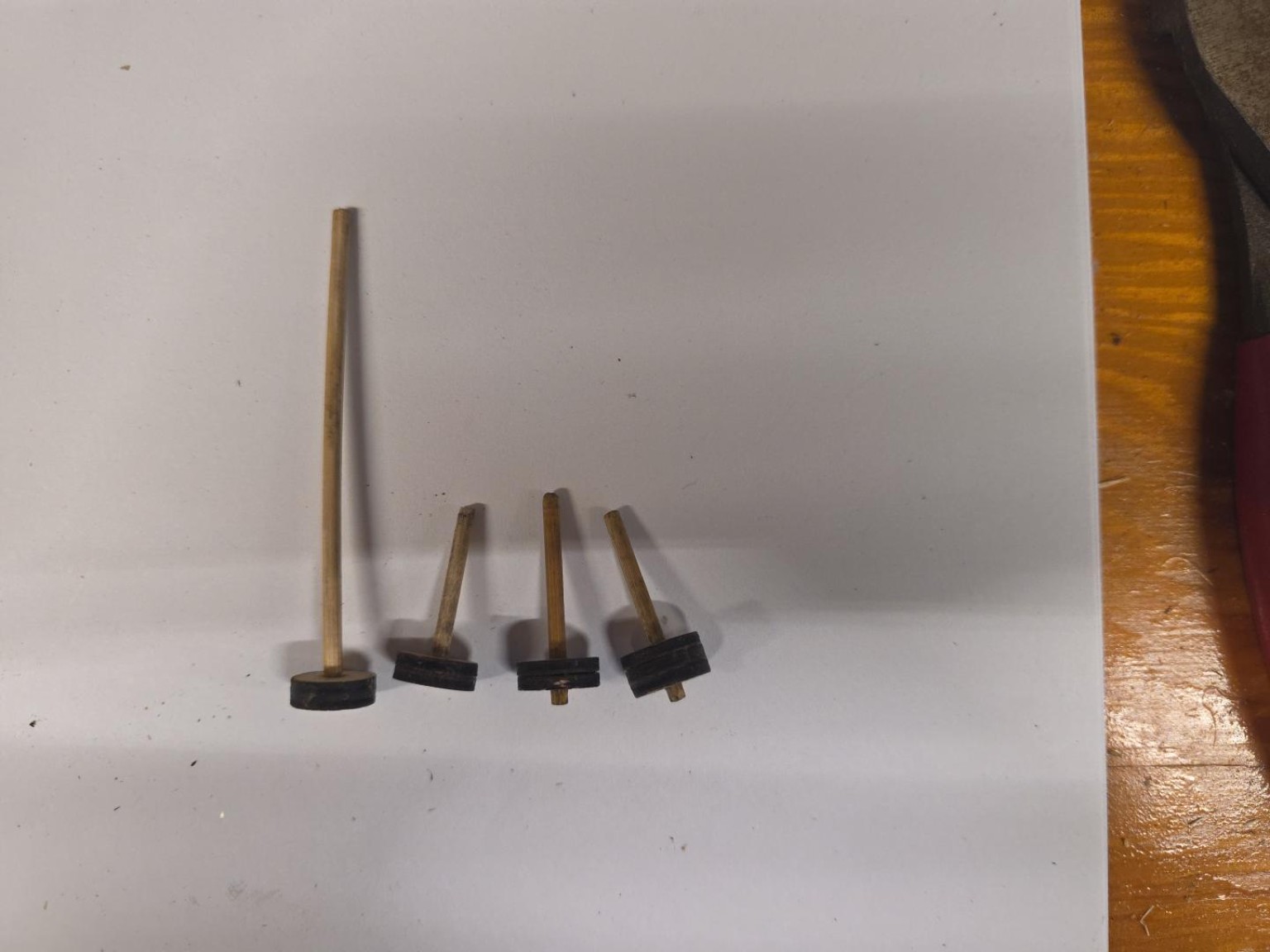
Compare your four pins with the photo. From left to right: • 85 mm, two rings, flat bottom. • 35 mm, two rings, flat bottom. • 35 mm, two rings, about 2.7 mm sticking out below. • 35 mm, three rings, about 2.7 mm sticking out below. Count nine rings in all. Check the ends and let the glue dry fully before packing or using the pins.
- Step 30 of 30
What we would try in the next batch
During production, we found that stacking at least two rings made the glued joint stronger. We cut the bamboo pieces one at a time. A future jig could hold several skewers at once for repeatable 35 mm and 85 mm cuts. It would need to hold each skewer firmly and give it a flat, square end.